
| เครื่องตั้งศูนย์ |
| ลิฟท์ยกรถยนต์ |
 ลิฟท์เปลี่ยนแบตเตอรี่ไฟฟ้า ลิฟท์เปลี่ยนแบตเตอรี่ไฟฟ้า |
| ถอดยาง-ถ่วงล้อ |
| เครื่องเติมลมยาง |
| เครื่องเจียรจานเบรค |
| อุปกรณ์น้ำมัน |
 เปลี่ยนถ่ายน้ำมันเกียร์ เปลี่ยนถ่ายน้ำมันเกียร์ |
| อุปกรณ์ไฮดรอลิค |
 เครืองถอดสปริงโช๊ค เครืองถอดสปริงโช๊ค |
| อุปกรณ์ลม |
 สว่านลม สว่านลม |
 ชุดเจียรคอตรง ชุดเจียรคอตรง |
| ตู้เครื่องมือช่าง |
| ปั๊มลม |
 ปั๊มลม Fusheng ปั๊มลม Fusheng |
 ปั๊มลม Tiger ปั๊มลม Tiger |
 ปั๊มลม Puma ปั๊มลม Puma |
| เครื่องเติมน้ำยาแอร์ |
| สายม้วน |
| =เมนู |
 Home Home |
 เกี่ยวกับแวพทูล เกี่ยวกับแวพทูล |
 สินค้ามาใหม่ สินค้ามาใหม่ |
 แผนที่บริษัทฯ แผนที่บริษัทฯ |
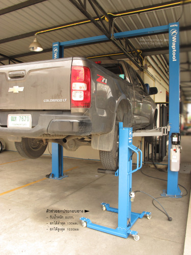
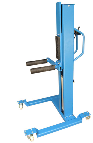
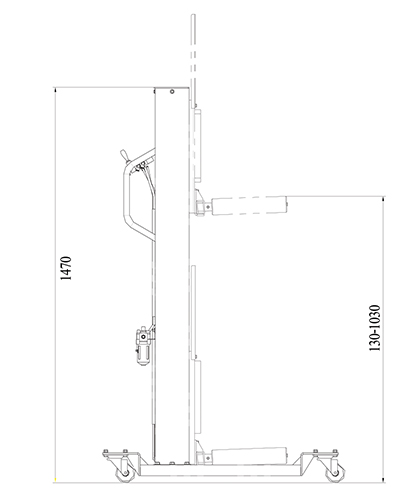
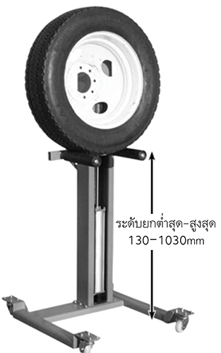
| เครื่องประกอบยกยาง แบบใช้ลม เครื่องยกประกอบยาง แบบใช้ลม เคลื่อนที่ได้ 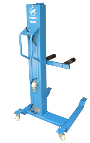 • รับน้ำหนัก : 80 กก. • รับน้ำหนัก : 80 กก. • ระดับยกสูงสุด : 1030 มม.
• ระดับยกต่ำสุด : 130 มม.
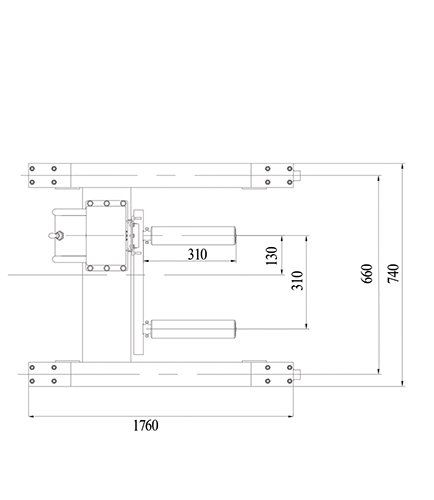
• ระยะห่างระหว่างแขน : 310 มม.
• แรงดันในการทำงาน : 8 ~ 10 bar
• ขนาดบรรจุภัณฑ์ : 1470x400x440 มม.
• น้ำหนักสินค้า : 71 kg.
• Lifting capacity : 80 kg
• Max. lifting height : 1030 mm • Min. lowered height : 130 kg • Arm length : 310 mm • Distance between two arms : 310 mm • Overall height : 1470 mm • Required compressed air pressure : 8 bar-10 bar • Weight : 71 kg • Packing dimension : 1470(L) x 400(W) x 440(H)
OPERATION AND USE
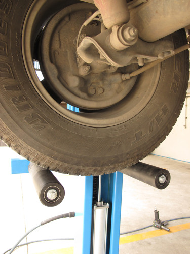
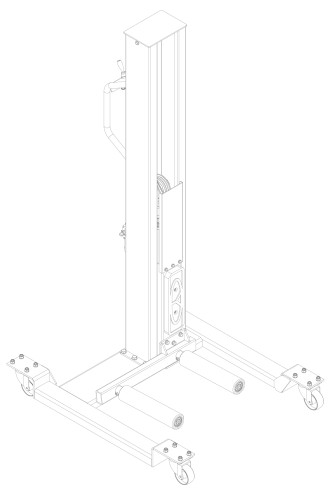  PNEUMATIC LINE CONNECTION PNEUMATIC LINE CONNECTIONThe pneumatic supply at site (to which the pneumatic system of the lift is connected) must be connected to the supplied lubricator. For the connection of the pneumatic lines proceed as follow: Mount the lubricator on the rear of the post; Connect the pneumatic lines pre-assembled to the lubricator; Connect the servicing unit to the pneumatic supply at site; Check the pneumatic control operations for proper performance. To operate the lift, do as follows: Move the lift close to the wheel to be lifted;
Put down the switch lever (ref. fig. 3) to let the lift lower at the minimum height;
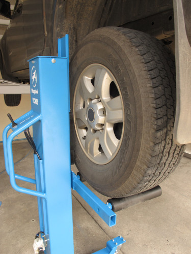
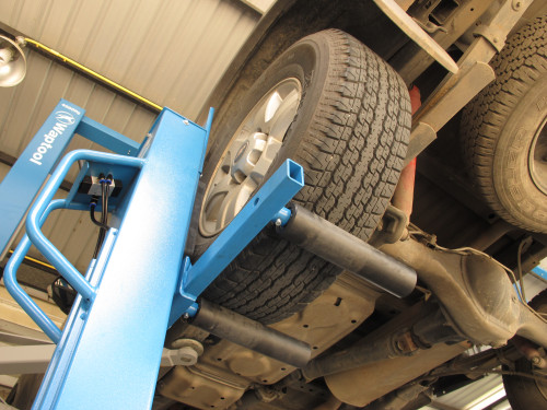
Place the wheel on the arms properly;
Raise the lift by putting up the switch lever (ref. fig. 3);
Rest the lift at a desired height by releasing the switch lever;
Place the wheel onto the tire changer or the wheel balancer carefully;
Move the lift out of the working space.
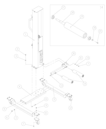 Figure3 - GENERAL ASSEMBLY 1.Column assembly 2.Screw M10X25
3.Washer D.10
4.Base
5.Left foot
6.Nut M10
7.Screw M8X20
8.Washer D.8
9.Nut M8
10.Screw M10X30
11.Right foot
12.Caster 3”
13.Screw M6X12
14.Wheel arm unit
15.Locking washer D.8
16.Arm support
17.Bearing 6203
18.Arm shaft
19.Arm roller
20.Washer D.8
21.Screw M8X16
|
เครื่องยกยางรถ
